12L14 Alloy Steel
6061-T6 Aluminum
Project case study
A mechanical design project that took a driveshaft system from concept to implementation, including geometry ideation, structural analysis, precision fixturing, and machining.
Overview
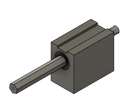
I designed, analyzed, and manufactured a precision driveshaft system for a high-performance wind turbine, focusing on structural integrity under maximum load conditions and tight-tolerance manufacturing.
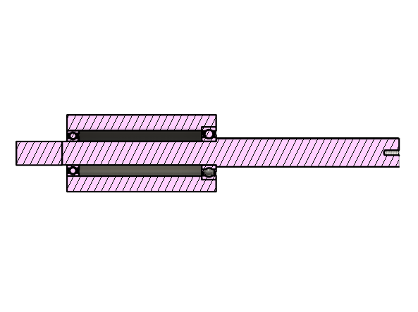
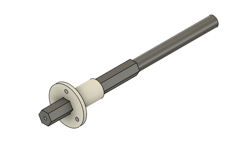
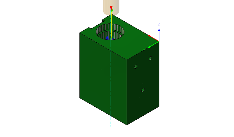
I selected bearings based on the load and speed requirements of the application, developed a bearing friction model, and designed and manufactured the bearing housing with precision press-fits. The system interfaced with the pitch mechanism subsystem through a PTFE bushing while transmitting torque to the generator.
12L14 Alloy Steel
6061-T6 Aluminum
Researched torque transmission methods and selected a hex shaft geometry for its cost-effectiveness and manufacturability. Bearing speed and load requirements drove the need for circular bore bearings, requiring circular shaft sections at the bearing interfaces. I used a two-bearing layout to maintain concentricity between the driveshaft and generator coupling.
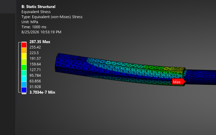
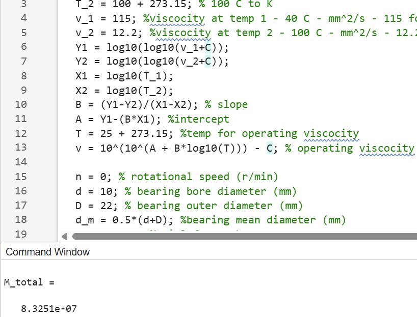
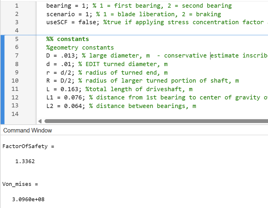
Developed a MATLAB stress model to evaluate von Mises stress in the shaft and guide geometry selection. Modeled the selected design in Fusion 360, validated the hand calculations with ANSYS FEA, and built a bearing friction model to support bearing selection. The bearing requirements informed the bearing block geometry, and the analyzed components were integrated into the full shaft subsystem assembly.
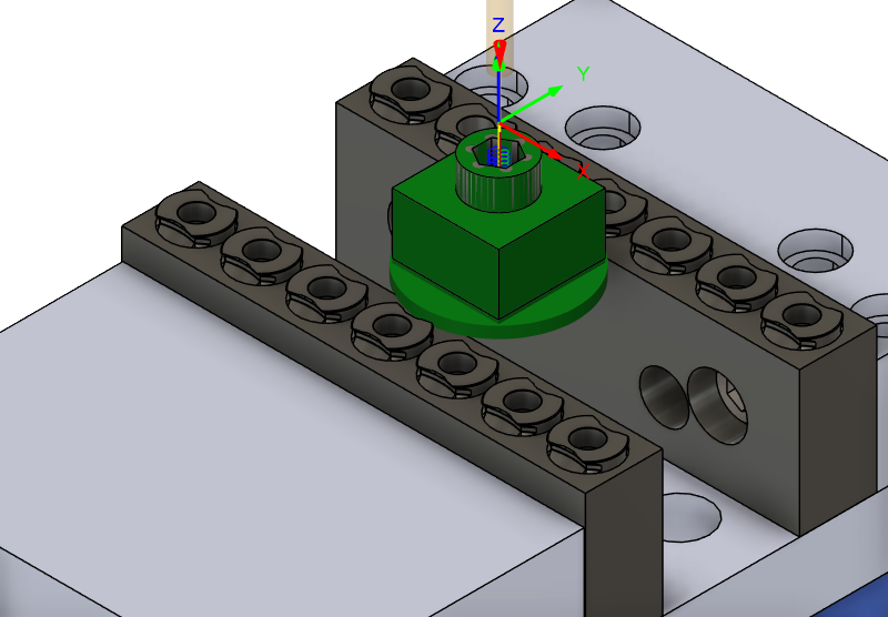
To improve machining setup accuracy, I designed and manufactured a custom fixture jig with a precision bore and exterior reference face. This addressed measurement challenges caused by the hex stock and provided a reliable locating surface to maintain concentricity between the hex and circular shaft sections.
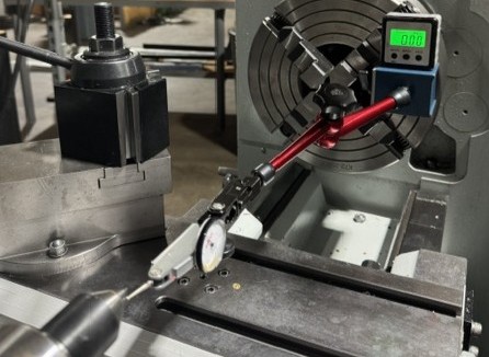
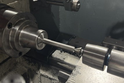
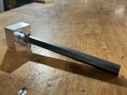
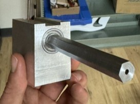
Manufactured the bearing block on a Haas TM CNC mill, machining the bore in a single workholding and using tool offset compensation to achieve the required press-fit tolerance. I machined the driveshaft on a manual lathe, indicating off of the fixture jig's locating surface and supporting the hex stock with a live center to reduce deflection.
Pressed the bearing into the block and installed the driveshaft through the bearing assembly. I verified shaft engagement, bearing alignment, and smooth rotation without binding.